5.3 Fuel System Diagram
Tm engine Farmall carburetor diagram cub fuel manual system carb farmallcub info parts gss float manuals galleries service lo boy section wiring Figure 2-1
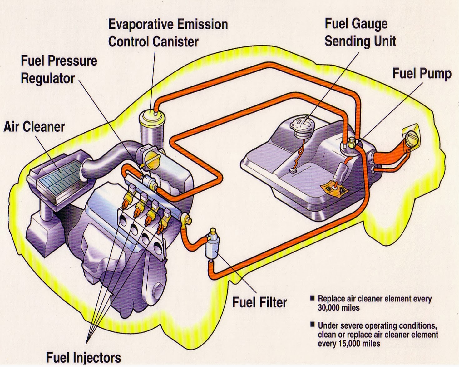
Figure 1-7. Fuel System Schematic
Fuel system diagram setup holden Figure 1-7. fuel system schematic Figure 1-28. fuel connections and controls.
Fuel system setup
A & a complete auto repair houstonFuel diagram system figure schematic Fuel system engine parts diesel diagram car feed components gasoline injection cars gas pump auto run look understanding anyone needsFuel cessna diagram 172r system 172 electric underside stem 1997 pump believe updates part stack.
Figure 1-7. engine fuel system componentsFuel system tm schematic figure change Figure 1-8. fuel system diagramArmyordnance tpub.


